
Carbon Fiber Composites in Wind Turbine Blades
The wind energy sector has undergone a remarkable transformation over the past two decades, with turbine rotor diameters expanding from modest 40-meter ranges to exceeding 120 meters for offshore installations. This growth has fundamentally altered the material requirements for blade construction. Traditional glass fiber reinforced polymer (GFRP) composites, while cost-effective for smaller turbines, face inherent limitations in stiffness and weight that become critical at larger scales.
Carbon fiber reinforced polymer (CFRP) composites have emerged as an enabling technology for next-generation wind turbine blades. Their exceptional specific stiffness, fatigue resistance, and tailorable properties allow engineers to design blades that are longer, lighter, and more efficient than what is possible with conventional materials. However, the adoption of carbon fiber in wind energy applications is not without challenges—cost constraints, manufacturing complexity, and specific failure mechanisms such as delamination and lightning susceptibility require careful consideration.
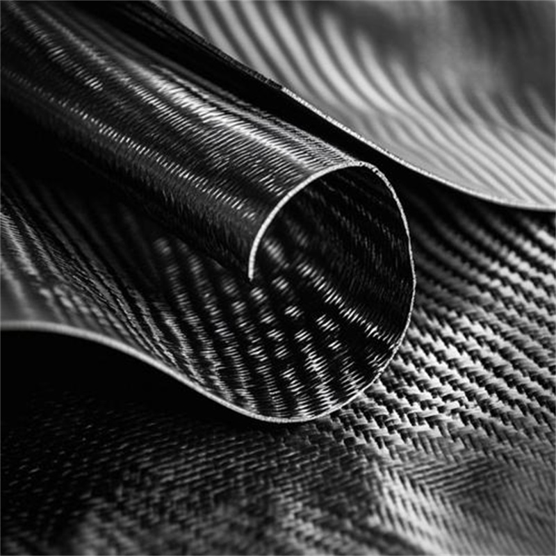
What Is Carbon Fiber Composite for Wind Turbine Blades?
Carbon fiber composite in the context of wind turbine blades refers to a structural material system consisting of carbon fiber reinforcements embedded in a polymer matrix, typically epoxy resin, engineered to meet the demanding mechanical and environmental requirements of large-scale wind energy applications.
The material is most commonly deployed in the blade’s primary load-bearing structure—the spar cap, which is the longitudinal reinforcement running along the blade’s length to resist bending moments. In modern designs, carbon fiber may also be used in hybrid configurations with glass fiber, combining the benefits of both reinforcement types.
Composition and Structure
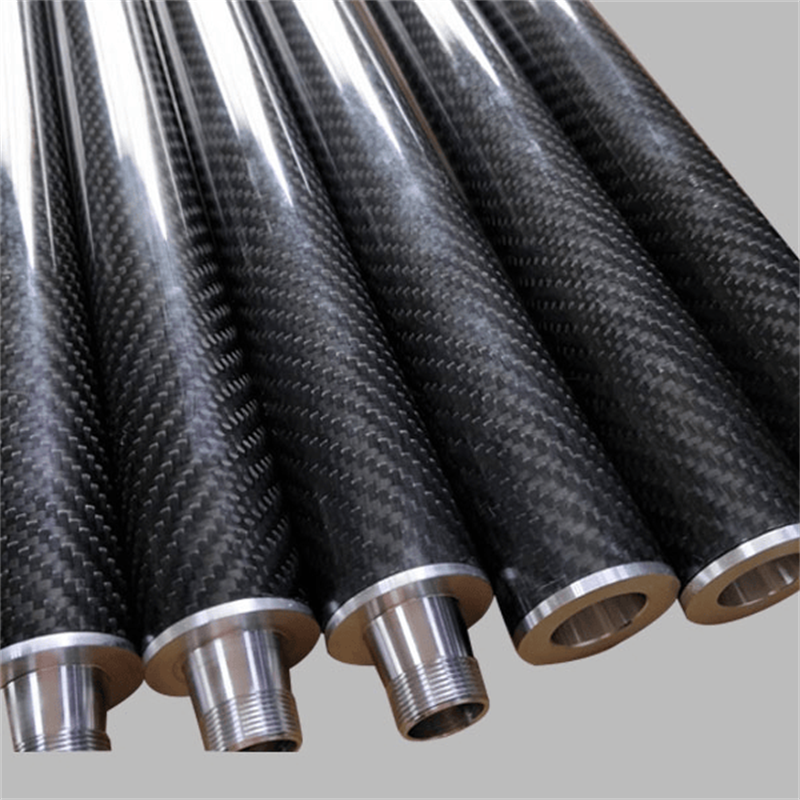
Reinforcement: The carbon fibers used in wind turbine blades are typically polyacrylonitrile (PAN)-based precursors, offering high strength and modulus. Standard modulus grades (about 230 GPa) are most common, with some applications utilizing intermediate modulus fibers. Fiber architectures include:
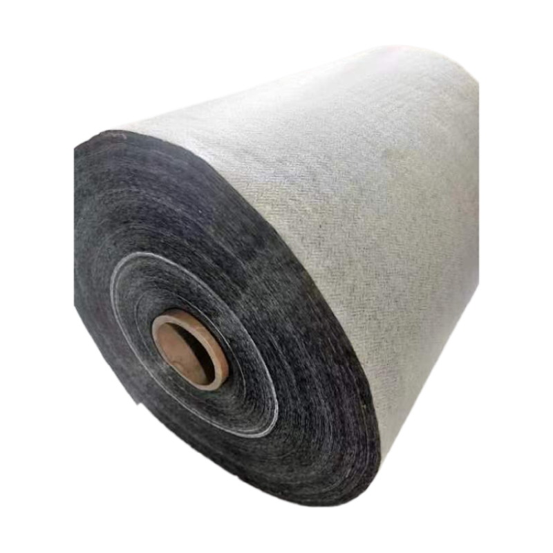
– Unidirectional (UD) fabrics or prepreg for maximum stiffness in the primary load direction
– Biaxial or multiaxial fabrics for shear and torsional resistance
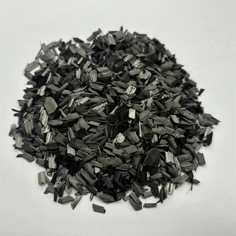
– Pultruded plates and preforms for streamlined manufacturing
Matrix: Epoxy resin is the predominant matrix system, offering excellent adhesion to carbon fibers, good fatigue properties, and processability through infusion and prepreg techniques. The choice of epoxy formulation influences curing temperature, viscosity, and fracture toughness.
Structural Configuration: The spar cap typically consists of multiple layers of carbon fiber laminates, with fiber orientation predominantly aligned with the blade span (0° direction). Off-axis plies at ±45° or other orientations may be included for load distribution, shear transfer, and sometimes to introduce beneficial coupling effects such as twist-flap coupling. Studies on off-axis carbon fiber application in spar caps indicate that optimized fiber angles near 7.5° can achieve twist-flap coupling more cost-effectively than the 20° previously reported in literature, while respecting constraints on cross-fiber and in-plane shear strength.
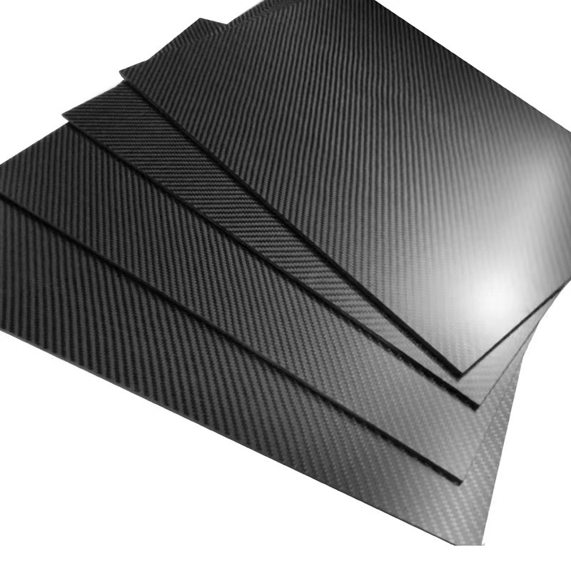
Manufacturing Processes for Carbon Fiber Blade Components
Several manufacturing methods are employed to produce carbon fiber components for wind turbine blades, each with distinct advantages and limitations.
Pultrusion
Pultrusion is increasingly favored for producing spar cap components, particularly in large-scale manufacturing. In this continuous process, resin-impregnated fiber tows are drawn through a heated die, where curing occurs, producing a constant cross-section profile.
Method: Hybrid pultrusion techniques can create plates containing both carbon and glass fibers. A two-step process may be used: first, carbon fiber preforms are pultruded separately, then combined with glass fiber tows in a second pultrusion die. This allows precise control over fiber architecture and positioning.
Advantages:
– High productivity and consistency
– Excellent fiber alignment and fiber volume fraction
– Reduced void content compared to infusion processes
– Ideal for producing long, straight spar cap profiles (typically 60–95% of blade length)
Applications: Pultruded carbon fiber plates serve as the primary reinforcement in spar caps, bonded into the blade shell during the main blade manufacturing process. The method allows even distribution of carbon and glass reinforcement, which is particularly important for lightning protection as carbon fibers’ high electrical conductivity requires careful management.
Prepreg Layup
Prepreg materials—pre-impregnated carbon fiber fabrics with partially cured resin—are used in some high-performance blade applications, particularly for smaller or more aerodynamically critical components.
Process: Layers of prepreg are placed in the mold according to a defined ply schedule, vacuum bagged, and cured in an autoclave or oven at elevated temperature.
Advantages: Precise fiber volume fraction control, excellent mechanical properties, and clean processing environment.
Limitations: Higher material cost, refrigerated storage requirements, and autoclave size constraints.
Vacuum-Assisted Resin Infusion
The predominant manufacturing method for complete wind turbine blades involves infusion of liquid resin into dry fiber preforms placed in large molds. For carbon fiber components, this process offers flexibility and scalability.
Process: Dry carbon fiber fabrics are laid into the mold, vacuum bagged, and liquid epoxy resin is drawn through the preform by vacuum pressure. The assembly is cured at ambient or moderately elevated temperature.
Considerations: Carbon fiber’s high electrical conductivity can pose challenges for infusion processes, particularly regarding lightning protection. The ability to integrate carbon fiber preforms with glass fiber sections in precise locations is a key capability.
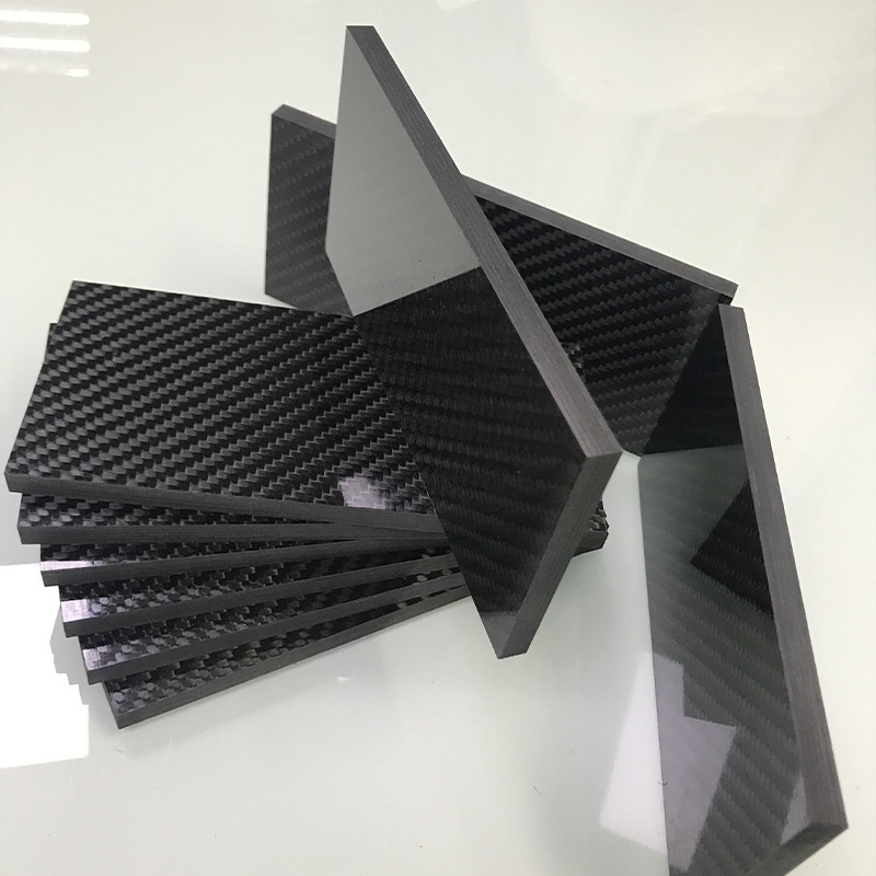
Key Properties of Carbon Fiber Composites for Wind Turbine Blades
Mechanical Properties
Specific Stiffness: Carbon fiber composites offer a specific stiffness (stiffness-to-weight ratio) approximately three to four times higher than glass fiber composites. This property is the primary driver for carbon fiber adoption, as increased stiffness allows longer blades without unacceptable weight penalties. For a 100-meter offshore blade, every kilogram of mass reduction in the spar cap translates to significant reductions in gravitational and inertial loads throughout the structure.
Tensile Strength: High-strength carbon fibers achieve ultimate tensile strengths exceeding 4,000 MPa at the fiber level, translating to composite strengths above 1,500 MPa in UD laminates. This allows the spar cap to withstand extreme loading events, such as storm gusts, without failure.
Fatigue Resistance: Carbon fiber composites exhibit excellent fatigue performance under the highly variable loading conditions experienced by wind turbine blades, which undergo millions of load cycles over their 20–25 year service life. The fatigue endurance limit for carbon fiber composites is typically higher than for glass fiber counterparts, enabling more conservative design margins or extended operational life.
Temperature-Dependent Behavior
The mechanical properties of CFRP for wind turbine blades vary significantly across the operating temperature range. Systematic evaluation of carbon fiber/epoxy composites for turbine blades across temperatures from -100°C to 140°C reveals distinct failure mechanism evolution. Understanding this full-temperature performance is essential for reliable blade design, particularly as offshore installations experience extreme temperature fluctuations.
Density
Carbon fiber composites typically exhibit densities of approximately 1.5–1.6 g/cm³, compared to 1.8–2.0 g/cm³ for glass fiber composites. This 15–25% density reduction contributes to the overall mass savings achieved by carbon fiber adoption.
Electrical Conductivity
Unlike glass fibers, carbon fibers are electrically conductive. While this property can be advantageous for some applications, it presents a specific challenge for wind turbine blades: carbon fiber composites are susceptible to lightning damage due to their ability to conduct high currents. This necessitates careful design of lightning protection systems, including appropriate fiber distribution in hybrid structures to prevent arcing over the spar cap.
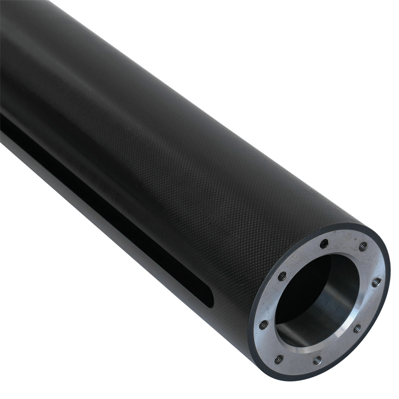
Advantages of Carbon Fiber Composites in Wind Turbine Blades
Extended Blade Length
The most significant advantage of carbon fiber composites is the ability to construct longer blades without exceeding mass and deflection constraints. Longer blades capture more energy—the theoretical power output increases with the square of the rotor diameter—making blade length a primary lever for turbine efficiency improvement.
For offshore wind turbines, where installation and maintenance costs are high, maximizing energy capture per turbine is economically critical. Carbon fiber enables the 100+ meter blades required for 10–15 MW offshore turbines.
Reduced Blade Mass
Lighter blades impose lower gravitational and inertial loads on the pitch system, bearings, and tower. This creates a cascading benefit: the entire support structure can be reduced in mass and cost, often outweighing the higher material cost of carbon fiber at the turbine system level.
Improved Fatigue Performance
The superior fatigue properties of carbon fiber composites contribute to longer blade service life and reduced maintenance requirements. For offshore installations, where maintenance access is expensive and weather-dependent, enhanced durability has significant economic benefits.
Tailorable Design
Composite design allows engineers to selectively orient carbon fibers to address specific loading conditions. Fibers can be aligned to:
– Maximize bending stiffness along the blade span
– Provide torsional stiffness for pitch stability
– Manage shear forces through the blade cross-section
– Introduce coupling effects such as twist-flap coupling that reduce aerodynamic loads
Structural Efficiency
Hybrid carbon/glass fiber designs offer optimized structural efficiency by placing higher-cost carbon fibers where they provide the greatest benefit. Research shows that increasing carbon fiber content in hybrid composites progressively enhances mechanical properties and torsional vibration resistance, contributing to longer blade service life. The carbon fiber ratio can vary along the blade span from approximately 0–20% at the root to 50–70% at the tip in some designs, placing reinforcement where loads and deflections are greatest.
Limitations and Challenges
Cost
Carbon fiber materials typically cost 5–10 times more than equivalent glass fibers on a per-kilogram basis. While system-level optimization often justifies this cost for large offshore turbines, the economic case for carbon fiber adoption in smaller turbines or cost-sensitive markets remains challenging.
Manufacturing Complexity
Carbon fiber processing requires more careful control than glass fiber, particularly for:
– Ply placement accuracy
– Void content control
– Temperature management during cure
– Quality assurance testing
The qualification process for new carbon fiber blade designs can extend to three years from initial specification to serial production, including three to six months for pre-production approval, with delays often occurring when customers need to adapt existing processes for new materials.
Delamination Risk
Carbon fiber composites are susceptible to interlaminar failure (delamination) during manufacturing or service. Studies investigating delamination in CFRP wind turbine laminates show that delamination alters strain behavior—reducing elastic modulus and Poisson’s ratio—and can lead to premature brittle failure in blades.
Delamination can originate from:
– Manufacturing defects (voids, contamination, improper cure)
– Impact damage during transport or service
– Cyclic loading-induced microcracking
– Environmental degradation
Lightning Protection
The high electrical conductivity of carbon fibers presents a lightning protection challenge. Direct lightning strikes can cause severe damage to carbon fiber components if not properly managed. Design strategies include integrating conductive meshes, using hybrid carbon/glass architectures to control current paths, and ensuring the spar cap design reduces risk of arcing across the spar beam.
Strain-to-Failure Mismatch
Carbon fibers have a lower strain-to-failure than glass fibers (approximately 1.5–2.0% for carbon vs. 3–5% for glass, depending on specific grades). This mismatch requires careful design of hybrid carbon/glass transitions to prevent stress concentrations and premature failure at the interface between materials with different strain capabilities.
Testing and Qualification
The rigorous testing requirements for wind turbine blades add significant time and cost to carbon fiber adoption. Certified testing facilities perform extensive evaluations of component materials and designs, including mechanical and fatigue examinations to validate compliance with Original Equipment Manufacturer (OEM) specifications. Materials are tested for durability under simulated operational conditions, including freeze-thaw cycling and high humidity exposure.
Applications in Wind Turbine Blades
Primary Applications
Spar Cap: The primary structural application of carbon fiber composites in wind turbine blades is in the spar cap, the main load-bearing element along the blade’s longitudinal axis. The spar cap resists the primary bending moment induced by aerodynamic loads, making it the most structurally critical component.
Shear Webs: Carbon fiber may be used in shear webs, the vertical or near-vertical structural elements connecting the upper and lower blade shells. Shear webs transmit shear forces and maintain blade cross-section shape.
Leading Edge Reinforcement: Some designs incorporate carbon fiber in the leading edge region for additional stiffness and impact resistance.
Root Joint: The blade root connection—where the blade attaches to the hub—may incorporate carbon fiber for weight reduction and load transfer efficiency.
Blade Design Configurations
Integrated Spar Cap: In this configuration, the spar cap is integrated into the blade shell during manufacturing, with carbon fiber layers built into the shell structure. This approach provides good load transfer and aerodynamic surface quality.
Pultruded Plate Insertion: An alternative approach uses pultruded carbon fiber plates bonded into the blade shell. This method offers manufacturing efficiency and quality consistency, with plates extending 60–95% of the blade length in some designs. The plates are arranged during lay-up and infused with polymer resin as part of the blade manufacturing process.
Hybrid Fiber Architecture: Many modern blades employ hybrid carbon/glass fiber architectures. The distribution of carbon fiber may be graded along the blade span, with higher carbon content toward the tip (where deflection control is most critical) and lower content near the root (where cost constraints are tighter). Total carbon fiber ratios in these hybrid structures typically range from 5% to 80%, with average ratios across stacked fiber layers commonly between 35% and 65%.
Scale Considerations
Onshore Turbines: Moderate adoption of carbon fiber, typically in blades 40–70 meters in length, often using hybrid architectures for cost optimization.
Offshore Turbines: Extensive carbon fiber use in blades exceeding 100 meters, where mass reduction and stiffness are paramount. Offshore blades must withstand immense loads and prevent excessive bending that could result in the blade striking the tower.
Small Turbines: Limited carbon fiber use due to cost constraints, though some high-performance small turbines incorporate carbon fiber for weight reduction and efficiency.

Industry Standards and Certification
The wind energy industry adheres to rigorous standards to ensure blade reliability and performance. Key standards applicable to carbon fiber composites in wind turbine blades include:
International Electrotechnical Commission (IEC)
IEC 61400-5:2020 – Wind energy generation systems – Part 5: Wind turbine blades. This standard specifies requirements for blade design, manufacturing, testing, and verification. All blade designs must meet performance standards including aerodynamic efficiency, strength, and fatigue resistance.
DNV Standards
DNV-ST-0376 – Standard for wind turbine blades, providing certification requirements and design guidelines for offshore and onshore applications.
China Standards
T/CI 476-2024 – Carbon fiber for wind turbine blade, specifying product classification, technical requirements, test methods, and packaging for carbon fiber materials used in wind turbine blades.
Quality Management
APQP4Wind – An industry initiative adapting Advanced Product Quality Planning (APQP) principles to the wind energy sector. This non-profit organization works to standardize quality assurance practices, reduce costs associated with non-quality, and accelerate time-to-market by standardizing documentation, testing, and quality assurance processes.
Testing and Certification
Qualification of carbon fiber blade components typically involves:
1. Material characterization – Testing of composite coupons to establish design allowables
2. Subcomponent testing – Evaluation of representative structural elements
3. Full-scale blade testing – Static and fatigue testing of complete blades
4. Certification body review – DNV or similar third-party verification
Pre-production approval typically lasts three to six months, with the transition from initial requirements to serial production potentially taking up to three years.
Design Considerations
Ply Orientation and Stacking
The design of carbon fiber laminates for spar caps requires careful selection of ply orientations and stacking sequence. The primary load direction (blade span) dominates, typically accounting for 70–90% of plies at 0°. Off-axis plies at ±45°, 90°, or other orientations provide:
– Shear transfer between blade sections
– Torsional stiffness and stability
– Load redistribution around cutouts or transitions
– Delamination resistance through interfacial toughness improvement
Delamination studies have shown that laminates with anti-symmetric fiber orientation exhibit higher buckling loads than those with symmetric orientation, while laminates with ply orientation variations demonstrate altered strain-related properties.
Fiber Volume Fraction
The fiber volume fraction in carbon fiber composites for wind turbine blades typically ranges from 50% to 65%, depending on the manufacturing process:
– Prepreg: 55–65%
– Infusion: 50–58%
– Pultrusion: 55–70%
Higher fiber volume fractions generally provide improved mechanical properties but may increase manufacturing difficulty and void content risk.
Hybrid Design Optimization
For hybrid carbon/glass configurations, optimization involves balancing:
Structural requirements:
– The carbon fiber ratio can be tailored along the blade span
– Carbon content may increase from near 0–20% at the blade root to 50–70% at the tip
– Average carbon fiber ratios across bearing structures commonly range from 35% to 65%
Economic constraints:
– Higher carbon content increases material cost
– Weight reduction benefits must outweigh material premium
Manufacturing considerations:
– Interface design between carbon and glass sections
– Process compatibility and quality assurance
Environmental Durability
Carbon fiber composites in wind turbine blades must withstand:
– Temperature extremes: -40°C to +60°C ambient, with significant heating due to solar radiation
– UV exposure: Coating and surface protection required
– Moisture ingress: Hydrolytic aging of epoxy matrix affects properties
– Saltwater exposure: Offshore installations require corrosion-resistant materials
– Lightning strikes: Lightning protection systems critical for carbon fiber components
Failure Mode Prevention
Delamination: Prevention strategies include:
– Optimized stacking sequences
– Through-thickness reinforcement
– Improved bonding surface preparation
– Process control to minimize defects
– Understanding strain-based failure mechanisms rather than relying solely on strength assessment
Fatigue: Design for fatigue life requires:
– Conservative stress levels below endurance limits
– Good surface finish to prevent crack initiation
– Adequate interlaminar shear strength
Brittle Failure: CFRP laminates in wind turbine blades exhibit brittle failure modes that can be catastrophic. Design approaches to mitigate premature brittle failure include ensuring adequate strain capacity in critical regions and understanding the relationships between delamination, buckling, and ultimate failure.
Selection Guide
When to Choose Carbon Fiber Composites
Turbine Size: For blades exceeding 70 meters in length, carbon fiber becomes increasingly necessary to meet stiffness and weight targets.
Offshore Applications: The higher capital and maintenance costs of offshore installations often justify carbon fiber’s premium for weight reduction and enhanced durability.
Performance Optimization: Projects requiring maximum energy capture, minimal tower mass, or extended blade length benefit from carbon fiber’s specific properties.
Weight-Sensitive Applications: Applications where blade weight significantly affects system cost, such as floating offshore turbines, benefit substantially from carbon fiber’s mass advantage.
When Carbon Fiber May Not Be Optimal
Small Turbines: For blades under 40 meters, the performance benefits of carbon fiber rarely justify the cost premium.
Cost-Sensitive Projects: Onshore projects with tight capital constraints may achieve better economics with optimized glass fiber designs.
Early-Stage Development: New turbine designs may initially use glass fiber while developing experience, transitioning to carbon fiber for later production variants.
Hybrid vs. Full Carbon
Hybrid Architecture: Most large blade designs employ hybrid carbon/glass fiber architectures, placing carbon fiber where stiffness and mass reduction provide maximum benefit while using lower-cost glass elsewhere.
Full Carbon: Some advanced designs use carbon fiber throughout the spar cap for maximum performance, though this approach is typically limited to the largest offshore turbines where cost is secondary to performance.
Key Selection Criteria
Mechanical Properties: Determine required stiffness, strength, and fatigue performance. Carbon fiber offers significant advantages in specific stiffness and fatigue life.
Manufacturing Capability: Assess available processes and quality control capabilities. Carbon fiber requires more careful processing.
Cost-Effectiveness: Evaluate total system cost, not just material cost. System-level optimization may show carbon fiber’s premium is justified.
Certification Requirements: Consider the qualification timeline and cost—carbon fiber solutions may require longer certification processes.
Operational Environment: Offshore, extreme climate, or other demanding applications favor carbon fiber’s durability.
Frequently Asked Questions
What is the primary reason for using carbon fiber composites in wind turbine blades?
The primary driver is the exceptional specific stiffness of carbon fiber composites, which allows the construction of longer, lighter blades without exceeding mass and deflection constraints. This directly contributes to higher energy capture and improved turbine efficiency.
How much weight reduction is achieved with carbon fiber compared to glass fiber?
Carbon fiber composites typically reduce blade mass by 15–30% compared to equivalent glass fiber designs, with greater savings in longer blades. Every kilogram of mass reduction in the spar cap produces cascading benefits throughout the turbine structure.
Is carbon fiber always superior to glass fiber for wind turbine blades?
No. Carbon fiber’s significantly higher material cost and manufacturing complexity mean glass fiber remains the preferred choice for smaller blades. The decision depends on turbine size, application (onshore vs. offshore), and cost targets. For blades below 40–50 meters, glass fiber is often the more economical choice.
What is a hybrid carbon/glass fiber blade?
A hybrid blade uses both carbon and glass fibers in different portions of the structure. Carbon fiber is typically placed in the spar cap where stiffness and weight reduction provide maximum benefit, while glass fiber is used where cost constraints are tighter. The carbon fiber ratio may vary along the blade’s span, increasing toward the tip.
How long does it take to qualify a new carbon fiber blade design?
The qualification process from initial specification to serial production can take up to three years. Pre-production approval alone typically lasts three to six months, with additional time for OEM manufacturing process adaptation and certification body approval.
What is delamination and why is it a concern for carbon fiber blades?
Delamination refers to separation between adjacent layers in a composite laminate. For carbon fiber wind turbine blades, delamination can alter strain behavior and lead to premature brittle failure. Preventing delamination requires careful process control, optimized stacking sequences, and robust design practices.
How are carbon fiber blades protected from lightning strikes?
Carbon fiber’s high electrical conductivity requires specific lightning protection measures. These include integrating conductive meshes, carefully designing fiber architecture to manage current paths, and employing hybrid carbon/glass designs to reduce arcing over structural components.
What standards apply to carbon fiber materials for wind turbine blades?
Key standards include IEC 61400-5:2020 (blade design and manufacturing requirements), DNV-ST-0376 (certification requirements), and T/CI 476-2024 (Chinese standard for carbon fiber for wind turbine blades). Quality management follows APQP4Wind principles.
Can carbon fiber blades be recycled at end of life?
Recycling carbon fiber composites remains challenging and more costly than glass fiber recycling. However, the industry is actively developing methods including pyrolysis, solvolysis, and mechanical recycling. The lower blade mass of carbon fiber designs also reduces the total material requiring disposal.
What are the main manufacturing processes for carbon fiber blade components?
The primary processes are pultrusion (for spar cap plates), prepreg layup (for high-performance components), and vacuum-assisted resin infusion (for complete blades). Pultrusion is increasingly favored for large-scale production due to its consistency and productivity.
Carbon fiber composites represent an enabling technology for the continued growth of wind energy, particularly for offshore installations where longer blades directly translate to improved economics. The material’s exceptional specific stiffness, fatigue resistance, and tailorable properties allow engineers to design blades that push the boundaries of what is structurally and economically feasible.
However, successful application of carbon fiber in wind turbine blades requires careful attention to the material’s limitations. Cost remains a significant barrier to broader adoption, manufacturing and certification processes require substantial lead time and investment, and specific failure modes such as delamination demand rigorous design and quality control.
The future of carbon fiber in wind energy lies in continued optimization of hybrid architectures, development of more cost-effective manufacturing processes, and improved understanding of failure mechanisms to enable more reliable designs. As turbine sizes continue to grow and offshore wind deployment accelerates, carbon fiber composites will play an increasingly central role in the industry’s evolution.
For engineers, procurement professionals, and researchers working in this field, understanding both the capabilities and constraints of carbon fiber composites is essential for making informed material decisions that balance performance, cost, and reliability across the complete turbine system.
 Metals vs. Ceramics vs. Composites: Engineer’s Guide to Material Selection
Material Selection Guide for Corrosive Environments
 Alloys vs. Ceramics vs. Polymers for High-Temperature Applications
 Comparative Analysis of Automotive Lightweighting Materials