
Why Is Carbon Fiber Composite Both Lightweight and Strong
In the traditional materials selection matrix, engineers have long faced a fundamental trade-off: high-strength materials tend to have high density (e.g., alloy steels), while low-density materials typically lack sufficient stiffness (e.g., aluminum alloys and conventional engineering plastics). Carbon fiber reinforced polymer (CFRP) has revolutionized the aerospace, automotive, and high-performance sports industries precisely because it fundamentally decouples the linear relationship between weight and strength.
For materials engineers, design engineers, and product developers, understanding CFRP’s true value lies not in memorizing that “it is light and strong,” but in mastering the quantitative advantages of specific stiffness and specific strength, and leveraging anisotropy for directional performance tailoring. This article provides an in-depth technical analysis grounded in atomic bond energy, composite effects, and industrial failure criteria, supported by hard performance data.
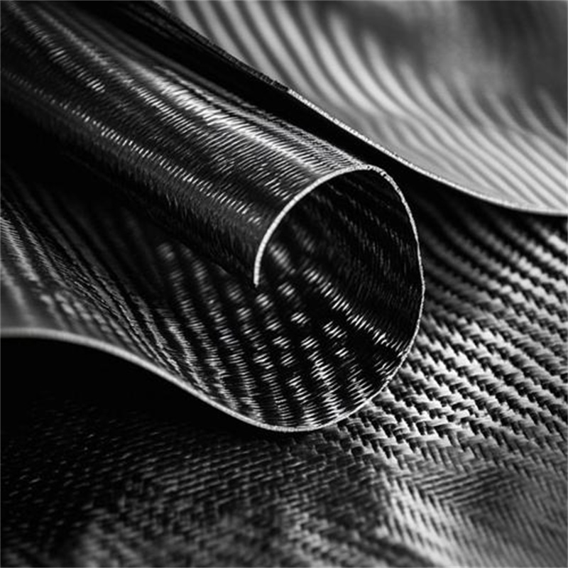
1. What Is Carbon Fiber Composite? — Definition and Material Architecture
Carbon fiber composite is a two-phase engineered material consisting of a reinforcing phase and a matrix phase. It is not a simple mixture but a synergistic system where the combination outperforms either constituent alone.
Reinforcement Phase (Carbon Fibers):
– Carbon content exceeding 92%, with a turbostratic graphitic microstructure
– Individual filament diameter: 5–8 μm (approximately 1/10 the diameter of a human hair)
– These microscopic filaments carry nearly the entire axial tensile load in the composite structure
Matrix Phase (Polymer):
– Typically thermosetting resins such as medium-temperature curing epoxy or high-temperature bismaleimide (BMI) systems
– Critical functions: maintaining fiber orientation, transferring shear loads between fibers, and protecting fibers from environmental degradation (moisture, UV, chemical attack)
The Composite Action:
The matrix binds the fibers into a coherent structural element and enables load transfer through interfacial shear stress. Without this interface, the fibers would behave like loose threads incapable of resisting compression or bending.
2. The Atomic and Microstructural Origins of Performance
To answer *why* carbon fiber composite is both light and strong, we must examine the material at the atomic scale.
Why Is It So Light? — The Physics of Low Density
Carbon has an atomic number of 6 and a small atomic radius. In the formation of graphitic microcrystals, carbon atoms arrange themselves in densely packed hexagonal layers. However, the interlayer spacing (0.335 nm) is relatively large, creating a structure that is both ordered and porous at the atomic level.
Quantitative Density Comparison:
– Carbon fiber: 1.78 – 2.10 g/cm³ (varies by grade and graphitization temperature)
– Epoxy resin matrix: 1.10 – 1.30 g/cm³
– CFRP laminate (typical 60% fiber volume fraction): 1.50 – 1.60 g/cm³
Benchmark against conventional metals:
– Cast aluminum alloy (A380): 2.71 g/cm³ — CFRP is approximately 42% lighter
– Structural steel (AISI 1020): 7.85 g/cm³ — CFRP is approximately 80% lighter
– Titanium alloy (Ti-6Al-4V): 4.43 g/cm³ — CFRP is approximately 65% lighter
For a given component volume, replacing steel with CFRP reduces mass by a factor of five. Replacing aluminum yields a weight saving of approximately 40–45%.
Why Is It So Strong? — The Chemistry of Covalent Bonding
The extraordinary strength of carbon fibers originates from the carbon-carbon covalent bond, one of the strongest chemical bonds in nature.
– Carbon-carbon bond energy: approximately 347 kJ/mol
– During high-temperature carbonization (1,500–3,000°C in an inert atmosphere), the hexagonal carbon rings become highly oriented along the fiber axis
When the fiber is loaded along its axis, the external force is transmitted directly to these strong covalent bonds. Unlike metals, which deform through dislocation slip and grain boundary migration, carbon fibers resist deformation through bond stretching — a much more energy-intensive process.
The Composite Effect: Why the Interface Defines Performance
Isolated carbon fibers are brittle and cannot resist bending or compression. The polymer matrix transforms them into a practical engineering material through interfacial shear stress transfer.
Critical Interface Metrics:
– Untreated carbon fiber-epoxy interfacial shear strength (IFSS): 30–50 MPa
– Surface-treated (anodized + sizing) IFSS: 80–100 MPa
– This 2–3× improvement directly translates to composite tensile strength and fatigue resistance
The fiber-matrix interface also acts as a crack arrester. In metals, a crack propagates unimpeded through the microstructure. In CFRP, the crack must navigate along the interface (requiring energy) or fracture fibers (requiring even more energy), providing multiple barriers to catastrophic failure.
3. Core Mechanical Properties — Quantitative Engineering Data
For mechanical engineers and R&D personnel conducting FEA and structural design, the following unidirectional (UD) lamina engineering constants serve as essential design inputs. All values assume a fiber volume fraction (Vf) of 55–60% and standard epoxy matrix.
Tensile Properties (0° — Fiber Direction)
This is where CFRP delivers its maximum performance.
– Standard-modulus grade (T300/epoxy): Tensile strength = 3,530 MPa; Tensile modulus = 230 GPa
– Intermediate-modulus grade (T800/epoxy): Tensile strength = 5,490 MPa; Tensile modulus = 294 GPa
– High-modulus grade (M55J/epoxy): Tensile strength = 4,020 MPa; Tensile modulus = 540 GPa
Engineering Reference: The tensile strength of 3,530 MPa is approximately 15 times higher than structural steel’s yield strength (~235 MPa for Q235 grade), while the density is only one-quarter that of steel.
Compressive Properties (0° — Fiber Direction)
Compression is the Achilles’ heel of CFRP. Under compressive loading, individual fibers undergo microbuckling before reaching their theoretical compressive capacity.
– Typical compressive strength: 1,200 – 1,800 MPa (approximately 60–80% of tensile strength)
– Compressive modulus: comparable to tensile modulus (230–290 GPa for standard grades)
Design Implication: Any structure subjected to significant compressive loads (e.g., fuselage skins, landing gear components) must be designed using compressive allowables, not tensile values.
Transverse Properties (90° — Perpendicular to Fibers)
Since the polymer matrix dominates transverse behavior, these properties are substantially lower.
– Transverse tensile strength: 40 – 80 MPa (fiber-dominated value: 3,530 MPa)
– Transverse tensile modulus: 8 – 12 GPa (fiber-dominated value: 230 GPa)
– Transverse compressive strength: 100 – 150 MPa
Critical Design Rule: CFRP is highly anisotropic. It must never be treated as an isotropic material analogous to metals. Load paths must be aligned with fiber orientations.
In-Plane Shear Properties
Shear behavior is governed by both matrix properties and fiber-matrix interface quality.
– In-plane shear strength: 80 – 120 MPa
– In-plane shear modulus: 4 – 6 GPa
4. Failure Modes and Fracture Mechanics
Understanding how CFRP fails is essential for safe, reliable design. Unlike metals, which exhibit ductile yielding and plastic deformation before fracture, CFRP displays brittle failure with multiple interacting damage mechanisms.
Dominant Failure Mechanisms
Delamination (Interlaminar Fracture):
– This is the most common fatigue-driven failure mode in laminated composites
– Since no fibers cross between plies, the matrix and interface must resist Mode I (opening) and Mode II (shearing) fracture
– Critical energy release rate (GIC): typically 200–500 J/m² for standard epoxy systems
– Delamination is particularly severe at free edges, hole boundaries, and ply drop-off regions
Matrix Cracking (Intralaminar Fracture):
– Occurs when transverse tensile or shear stresses exceed matrix strength
– Initial microcracks appear at strains of 0.3–0.5%
– At critical strain (approximately 1.5–2.0%), matrix cracking coalesces and triggers fiber breakage
Fiber Breakage:
– The ultimate failure mode under axial overload
– Occurs when tensile strain exceeds approximately 1.5–2.0% (depending on fiber grade)
– Fiber breakage is catastrophic and often propagates instantaneously through the cross-section
Damage Tolerance Considerations
Unlike metals, which show visible deformation before failure, CFRP provides limited visual warning. However, the multiple crack propagation barriers (fiber-matrix interfaces, ply boundaries) provide excellent damage tolerance under cyclic loading.
Fatigue Performance:
– CFRP retains 60–80% of its static tensile strength after 10⁷ cycles at typical service stress levels
– Conventional aluminum alloys retain approximately 30–50% under equivalent conditions
– This makes CFRP ideal for infinite-life design in aerospace structures
5. Quantified Performance Advantages Over Metals
When evaluating CFRP against conventional engineering metals, the following quantitative differentiators are most significant for engineering decision-making.
Specific Stiffness (E/ρ) — The Lightweighting Enabler
Specific stiffness determines how much deflection occurs under load for a given component weight.
– High-modulus CFRP (M55J grade): E/ρ ≈ 187 GPa·cm³/g
– Steel (AISI 1020): E/ρ ≈ 26 GPa·cm³/g
– Aluminum alloy (7075-T6): E/ρ ≈ 26 GPa·cm³/g
Engineering Implication: To achieve identical bending stiffness, a CFRP component weighing only 30–50% of a steel or aluminum component can be designed. This is the fundamental basis for weight reduction in aircraft structures.
Specific Strength (σ/ρ) — The Load-Carrying Metric
Specific strength determines how much load a component can carry per unit weight.
– Intermediate-modulus CFRP (T800/epoxy): σ/ρ ≈ 2,000–2,200 MPa·cm³/g
– Steel (AISI 1020): σ/ρ ≈ 59 MPa·cm³/g
– Aluminum alloy (7075-T6): σ/ρ ≈ 167 MPa·cm³/g
Quantified Advantage: CFRP’s specific strength is approximately 20× higher than steel and 10–12× higher than aluminum on a weight-for-weight basis.
Thermal Dimensional Stability (CTE)
– CFRP (fiber direction): Coefficient of thermal expansion (CTE) = -0.5 to +1.0 × 10⁻⁶/°C (near-zero or slightly negative)
– Steel: CTE ≈ 12 × 10⁻⁶/°C
– Aluminum: CTE ≈ 23 × 10⁻⁶/°C
Critical Application: In precision instruments (space telescopes, coordinate measuring machines) and large aerospace structures, CFRP maintains dimensional accuracy across temperature extremes, eliminating thermal mismatch issues.
6. Industry-Specific Applications and Material Selection Criteria
Carbon fiber composite is not a universal replacement for metal — it is a mission-specific engineered solution. The following applications illustrate how material properties are matched to specific engineering demands.
Aerospace Primary Structures
Typical Components: Wing skins, fuselage barrel sections, center wing boxes (e.g., Boeing 787, Airbus A350)
Material Selection:
– Intermediate-modulus, high-toughness toughened epoxy prepreg (T800-grade fiber / 3900-2 system)
– Unidirectional tape with fiber areal weight (FAW) of 150 g/m² or 300 g/m²
– Quasi-isotropic layup sequence: [45/0/-45/90]s or [0/45/90/-45]s for balanced in-plane properties
Performance Achieved:
– Boeing 787 achieved a 20% reduction in structural weight compared to conventional aluminum designs
– Fuel efficiency improvement: 10–12% over comparable aluminum aircraft
– Fatigue design life: 44,000 pressurization cycles (exceeding metal counterparts)
Design Criticalities:
– Automatic fiber placement (AFP) used to minimize splice joints and improve manufacturing consistency
– Titanium alloy laminates (Ti-CFRP hybrid) employed at bolted joint locations to mitigate bearing stress concentrations
– Copper mesh or aluminum expanded foil embedded in the outer ply for lightning strike protection (CFRP’s high electrical resistance prevents adequate charge dissipation otherwise)
Hydrogen Storage — Type IV and V Pressure Vessels
Typical Components: High-pressure hydrogen storage tanks for fuel cell vehicles and aerospace applications (35 MPa to 70 MPa working pressure)
Material Selection:
– T700-grade (standard modulus, high-strength) or T800-grade fibers for cost-performance balance
– High-toughness wet-winding epoxy resin systems with extended pot life
– Filament winding process with helical and hoop winding patterns
Performance Achieved:
– Design burst pressure: 2.25× working pressure (minimum 157.5 MPa for 70 MPa vessels)
– Operating stress in fibers: 2,500–2,800 MPa (approaching fiber ultimate strength)
– Gravimetric hydrogen storage density: 4.5–6.5 wt.% (significantly higher than metal-lined Type III vessels)
Winding Architecture:
– Helical winding at ±15° to ±30° to withstand axial loads and pressurization-induced end loads
– Hoop winding at 90° to resist circumferential (hoop) stress, which is twice the axial stress per thin-wall pressure vessel theory
– Typical thickness for 70 MPa vessel: 20–40 mm (depending on diameter and burst margin requirements)
Automotive Lightweighting — Structural and Drivetrain
Typical Components: Propeller shafts, leaf springs, battery enclosures, and crash structures
Material Selection:
– Propeller shafts: High-strength intermediate-modulus fibers for torsional stiffness
– Leaf springs: Glass-carbon hybrid composites to balance cost, damping, and durability
– Battery enclosures: Standard-modulus fabrics with flame-retardant resin systems (UL94 V-0 rating)
Performance Achieved — Propeller Shafts:
– Weight reduction: 60% compared to steel shafts
– Critical rotational speed (Ncrit) increased by 40% — significantly reducing NVH (noise, vibration, harshness) at highway speeds
– Torsional strength: designed for 1,500–2,000 Nm torque capacity (passenger vehicle) or >5,000 Nm (heavy-duty)
Performance Achieved — Battery Enclosures (EVs):
– Weight reduction: 40–50% compared to steel stampings
– Thermal conductivity: fiber orientation enables directional heat dissipation away from battery cells
– Impact resistance: CFRP enclosures absorb 2–3× more impact energy per unit weight than steel during side-pole impacts
Medical Imaging Equipment
Typical Components: CT scanner patient tables, mobile X-ray housing, MRI head coils
Material Selection:
– Ultra-low CTE carbon fiber grades to maintain calibration accuracy
– High-transparency epoxy matrices optimized for radiographic clarity
Performance Achieved:
– X-ray absorption: CFRP absorbs approximately 1/3 the radiation of aluminum, reducing patient exposure
– MRI compatibility: CFRP produces no eddy currents in 1.5T to 3.0T fields (unlike metals), eliminating image distortion
– Structural stiffness-to-weight ratio: patient tables achieve 500–800 kg load capacity with minimal deflection (<2 mm at full load)

7. Procurement and Specification Guide — Quantifiable Selection Criteria
For purchasing managers, buyers, and procurement engineers, specifying carbon fiber composite requires precise, measurable parameters. The following criteria distinguish professional specifications from vague material requisitions.
Fiber Areal Weight (FAW) — Units: g/m²
This defines the weight of dry fiber per unit area in the prepreg or fabric.
– Standard unidirectional prepreg tapes: 150 g/m² (cured ply thickness ≈ 0.125 mm) or 300 g/m² (≈ 0.25 mm)
– Woven fabrics (plain, twill, satin): 200 g/m², 400 g/m², or 600 g/m²
Procurement Impact:
FAW determines the final laminate thickness and fiber volume fraction for a given number of plies. Using 150 g/m² tape allows finer control over thickness and mechanical properties than 300 g/m², but increases labor or layup time.
Resin Content (RC) — Units: Weight %
This defines the weight percentage of the polymer matrix relative to total prepreg weight.
– Structural-grade aerospace prepregs: 32–36% resin content
– Automotive/rapid-cure prepregs: 35–40% (higher resin aids rapid mold filling)
– Wet-winding systems: 28–32% resin content after cure (higher fiber volume fraction)
Procurement Impact:
Resin content directly determines the fiber volume fraction (Vf).
– Vf = (fiber density × FAW) / (total laminate thickness × composite density)
– Optimal Vf for structural performance: 55–60%
– Vf below 50%: matrix-dominated, lower strength and modulus
– Vf above 65%: risk of incomplete fiber wetting, voids, and poor interlaminar properties
Glass Transition Temperature (Tg) — Units: °C
Tg defines the temperature at which the polymer matrix transitions from a glassy, rigid state to a rubbery, compliant state — mechanical properties degrade significantly above Tg.
– Aerospace-grade thermosets: Tg > 180°C (requires post-cure at 190–200°C)
– Automotive-grade fast-cure epoxies: Tg = 130–150°C (cure cycle: 3–5 minutes at 150°C)
– High-temperature polyimides: Tg > 300°C (for hypersonic and supersonic applications)
Procurement Impact:
The maximum continuous service temperature must remain at least 30–40°C below Tg. Exceeding Tg accelerates creep deformation and reduces fatigue life by orders of magnitude.
Out-Life and Shelf-Life — Units: Days/Months
Prepreg materials have finite handling and storage windows.
– Shelf-life (frozen storage at -18°C): 6–12 months (depending on resin system)
– Out-life (room temperature handling, 21–23°C): 20–30 working days for standard epoxies
– High-tack aerospace prepregs may have out-life as short as 10–15 days
Procurement Impact:
Logistics and manufacturing schedules must account for out-life expiration. Expired prepreg must be requalified or scrapped, adding significant cost. Specify lower out-life materials only when necessary for specific processing benefits.
Void Content — Units: Volume %
Voids are microscopic air pockets trapped in the laminate during cure. They act as stress concentrators and degrade mechanical properties.
– Aerospace-grade laminates: void content < 1% (autoclave-cured)
– Automotive-grade (out-of-autoclave): void content < 2% (acceptable for non-primary structures)
– Research-grade (laboratory): void content < 0.5% (vacuum-bag cured with careful degassing)
Procurement Impact:
Void content affects interlaminar shear strength most significantly. For any safety-critical structure, specify nondestructive inspection (ultrasonic C-scan or X-ray micro-CT) to verify void content before acceptance.
8. Common Engineering Misconceptions and Pitfalls
Even experienced engineers can misunderstand or misapply CFRP. The following clarifications are critical for successful project execution.
Misconception 1: CFRP is electrically conductive and provides adequate grounding.
– Correction: Carbon fibers are conductive along their axial direction but have very high transverse electrical resistivity (10–100× higher than axial resistivity).
– For lightning strike protection on aircraft, or for EMI shielding in sensitive electronics, an embedded copper mesh or aluminum expanded foil layer is mandatory. Without it, lightning current cannot dissipate effectively, causing localized heating and delamination.
Misconception 2: CFRP will always have higher stiffness than metals because it’s “stronger.”
– Correction: Standard-modulus carbon fiber (T300 grade) has a tensile modulus of 230 GPa — essentially identical to steel’s 210 GPa.
– Replacing an aluminum component with T300 CFRP of identical thickness will yield only marginal stiffness improvement, despite massive strength improvement.
– For stiffness-critical applications (e.g., machine tool spindles, precision frames), specify high-modulus or ultra-high-modulus fibers (M40J, M55J, M60J) with modulus values of 400–700 GPa.
Misconception 3: CFRP can be welded or injection-molded like plastics.
– Correction: Thermoset CFRP is not weldable and cannot be injection-molded (injection molding applies to short-fiber thermoplastics, not continuous fiber composites).
– Joints must be designed using:
– Mechanical fastening (bolts, rivets, Hi-Loks) — with extensive bearing strength testing
– Adhesive bonding — requiring strict surface preparation (abrasion + solvent wipe, or plasma treatment)
– Without proper surface preparation, adhesive bond strength achieves only 20–30% of its theoretical maximum, risking premature joint failure.
Misconception 4: More fiber always means stronger composite.
– Correction: Fiber volume fraction (Vf) above 65% creates processing problems.
– Insufficient matrix prevents complete wetting of the fiber bundle, trapping air voids.
– These voids reduce interlaminar shear strength and create stress concentrators.
– The optimal window for structural CFRP is 55–60% Vf.
9. Industry Standards and Test Methods
For compliance and quality assurance, reference the following standards during material qualification and component validation:
Tensile Testing:
– ASTM D3039 — Standard test method for tensile properties of polymer matrix composite materials
– ISO 527-4 — Determination of tensile properties for isotropic and orthotropic composites
Compression Testing:
– ASTM D3410 — Compressive properties of polymer matrix composites with unsupported gauge section
– ASTM D6641 — Combined loading compression (CLC) test method
Shear Testing:
– ASTM D3518 — In-plane shear response of polymer matrix composites by ±45° tension test
– ASTM D5379 — V-notched rail shear method for shear properties
Flexural Testing:
– ASTM D7264 — Flexural properties of polymer matrix composites (3-point or 4-point bending)
Fracture Toughness:
– ASTM D5528 — Mode I interlaminar fracture toughness (DCB test)
– ASTM D6671 — Mixed-mode interlaminar fracture toughness
Non-Destructive Inspection (NDI):
– Ultrasonic C-scan (pulse-echo or through-transmission) for detecting delaminations and voids
– X-ray micro-CT for detailed void characterization
– Shearography for bond-line inspection in repair applications
10. Final Engineering Perspective
Carbon fiber reinforced polymer has earned its place in the advanced manufacturing toolkit not through marketing hype, but through quantifiable, repeatable performance metrics that cannot be matched by conventional metals in weight-critical applications.
The numerical case for CFRP is clear:
– Specific strength: approximately 20× that of steel and 10–12× that of aluminum
– Specific stiffness: up to 7× that of steel or aluminum (with high-modulus fiber grades)
– Fatigue endurance: 60–80% of ultimate strength retained after 10⁷ cycles
– Corrosion and environmental resistance: eliminating the cost and weight of protective coatings
However, CFRP remains a specialist material, not a universal substitute.
– Design complexity is higher due to anisotropy
– Manufacturing defects (voids, wrinkles, misalignment) degrade performance more severely than in metals
– Repair requires specialized skills and equipment
– Material cost remains 5–20× higher than steel or aluminum (depending on fiber grade and matrix system)
For the engineering team, success with CFRP demands:
– Alignment of primary loads with fiber orientation (concurrent design of structure and layup)
– Careful selection of fiber modulus grade and resin Tg to match the service environment
– Rigorous quality control through every step of manufacturing
– Realistic acceptance of cost and schedule implications
When applied correctly, CFRP is not merely a lightweight substitute for metal — it is an enabling technology that makes possible structures and performance levels that are simply impossible with conventional materials.
Frequently Asked Questions (FAQ)
How can carbon fiber be stronger than steel if carbon is such a common element?
The strength comes from the covalent bond arrangement, not from elemental rarity. Carbon-carbon covalent bonds are exceptionally strong (347 kJ/mol bond energy). When millions of these bonds are aligned along the fiber axis during high-temperature graphitization, the resulting tensile strength (3,500–6,000+ MPa) far exceeds the yield strength of typical steel grades.
Is carbon fiber composite always lighter than aluminum for the same component?
Yes, for the same component volume, CFRP is approximately 40–45% lighter than aluminum. However, for the same structural performance, the weight saving can be 50–70% because CFRP’s specific stiffness and specific strength are significantly higher.
What is the maximum service temperature for carbon fiber composites?
This depends entirely on the matrix system. Standard epoxies: 80–150°C; high-temperature epoxies: 150–200°C; polyimides/bismaleimides: 250–350°C. Carbon fibers themselves remain stable up to 3,000°C in inert atmospheres, but the matrix softens at much lower temperatures.
Can I use standard metal-cutting tools to machine CFRP?
Not recommended. Standard tools cause delamination, fiber pullout, and rapid wear. Use diamond-coated carbide tools with high cutting speeds and proper coolant application. Drill entry and exit are particularly vulnerable — use backup plates and backing materials to prevent exit-side delamination.
Does moisture affect carbon fiber composite performance?
Moisture absorption is a matrix-dominated phenomenon. Epoxies absorb 0.5–2.0% moisture by weight at saturation. This can reduce Tg by 15–30°C and cause swelling-induced microcracking. Aerospace-grade systems use moisture-resistant formulations and apply protective coatings to critical surfaces.
Why can’t I weld CFRP like metal?
Thermoset matrices are cross-linked polymers — they do not melt upon heating but instead degrade (char/burn) above their decomposition temperature (~300–400°C). Mechanical fastening (bolting, riveting) and adhesive bonding are the only practical joining methods.
What is the difference between standard-modulus and high-modulus carbon fiber?
Standard-modulus (T300, T700): tensile modulus ~230 GPa; optimized for strength. High-modulus (M40, M55, M60): tensile modulus 400–700 GPa; optimized for stiffness and dimensional stability, but at reduced strength (3,500–4,000 MPa vs. 5,000+ MPa for T800). Choose based on whether load-carrying or deformation resistance is the primary design driver.
How should I clean CFRP surfaces before adhesive bonding?
Abrasion (sanding or grit blasting) to remove the surface resin layer and create micro-mechanical interlocking, followed by solvent wiping with acetone or MEK to remove contaminants. Plasma treatment or corona treatment is recommended for optimal bond strength in aerospace applications. Do not use silicone-based mold release agents anywhere near bonding surfaces.
Is carbon fiber composite recyclable?
Recycling is technically possible but not yet widely economical. Methods include pyrolysis (recovering fibers by burning off the matrix) and supercritical fluid processing. Recovered fibers typically have 80–90% of virgin tensile strength and are used in non-primary structures (automotive interior components, consumer goods). Landfill remains the most common end-of-life disposition.
What are the warning signs of carbon fiber composite damage?
Unlike metals, CFRP does not show permanent plastic deformation (denting or necking). Visible damage indicators include: surface cracking, discoloration (white or yellow patches indicating matrix microcracking), delamination detected by coin-tap testing (dull sound indicates separation), and dimensional changes (thermal expansion mismatches causing warping). For safety-critical structures, perform ultrasonic C-scan inspections at regular intervals.
How do I prevent galvanic corrosion when CFRP contacts aluminum?
Carbon fiber is cathodic (noble) while aluminum is anodic. In the presence of moisture, a galvanic cell forms and rapidly corrodes aluminum. Use: (1) glass fiber or aramid scrim layers at the interface; (2) anodized aluminum surfaces; or (3) polysulfide sealants to exclude moisture. Direct metal-to-carbon contact must be avoided in any outdoor or wet-service application.
Why does CFRP cost so much more than fiberglass?
Carbon fiber production is energy-intensive (carbonization requires temperatures above 1,500°C) and requires expensive precursor materials (PAN-based acrylonitrile). Fiberglass production is a much lower-temperature, higher-speed process using abundant raw materials (silica sand). On a per-kilogram basis, carbon fiber is typically 5–10× more expensive than E-glass fiber. However, the performance benefit often justifies the cost in weight-critical applications.
All mechanical property values provided in this article represent typical reference data based on standard test coupons under laboratory conditions. Actual design allowable values for production components must be determined through specific material qualification testing in accordance with applicable industry standards (e.g., CMH-17 Composite Materials Handbook, ASTM/ISO methods, or FAA/EASA certification requirements). Engineers must apply appropriate safety factors and knockdown factors (environmental, manufacturing, and statistical) as prescribed by their design codes and regulatory framework. The author and publisher assume no liability for design decisions based on the data presented herein.
Carbon Fiber vs Glass Fiber Composites
The Influence of Fiber Orientation on the Mechanical Performance of Composite Laminates
 The Multifunctionality of Polymer Composites
 Thermoplastic vs. Thermoset Composites