
The Influence of Fiber Orientation on the Mechanical Performance of Composite Laminates
Composite materials, particularly laminated composites, offer a unique advantage over traditional monolithic materials: anisotropy. Unlike metals, which typically exhibit uniform properties in all directions (isotropy), composites can be engineered to have specific properties in specific directions. This directional tailoring is primarily achieved through the orientation of reinforcing fibers within the laminate structure.
For engineers and product designers, understanding the relationship between fiber orientation and mechanical performance is not merely an academic exercise; it is the foundation of effective composite design. The ability to align fibers precisely with expected loads allows for the creation of lightweight structures with exceptional strength, stiffness, and durability. This article provides a comprehensive, engineering-focused examination of how ply orientation influences the mechanical properties of composite laminates, drawing on established materials science principles and current research.
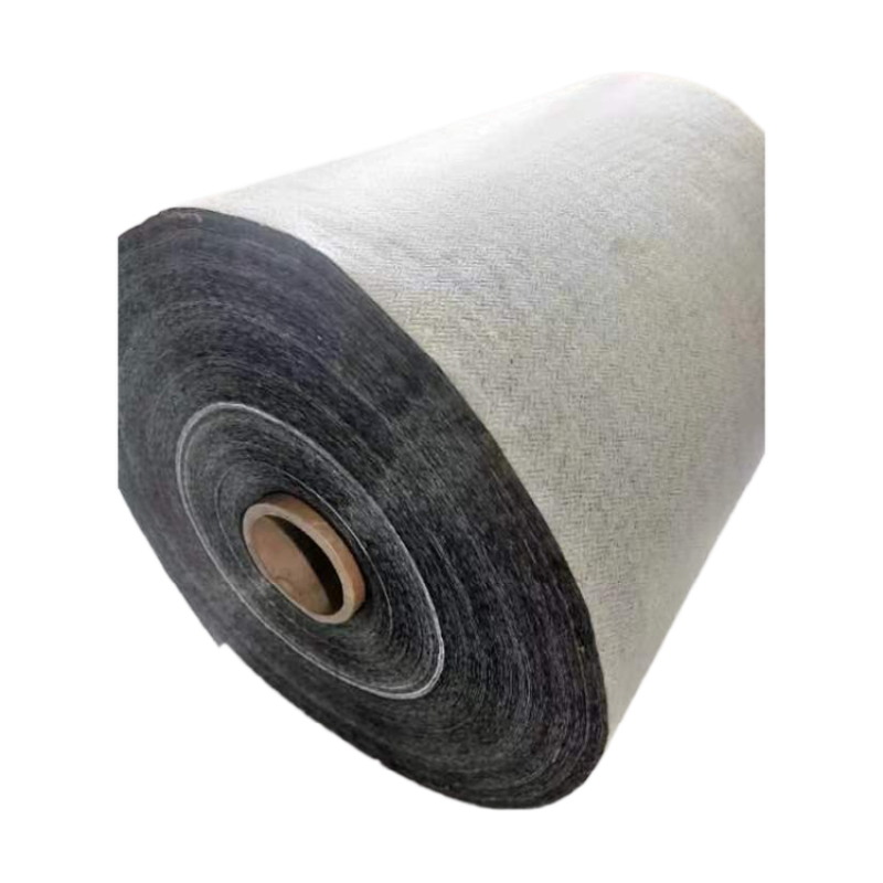
What Is a Composite Laminate?
Composite laminate is a layered structure constructed by stacking multiple thin layers of material, known as plies or laminae. Each ply typically consists of high-strength, high-stiffness fibers (e.g., carbon, glass, aramid) embedded within a polymer matrix material (e.g., epoxy, polyester).
The foundational principle of a laminate is that the orientation of the fibers in each ply can be varied. This creates a multi-directional material system capable of withstanding complex, multi-axial loads more effectively than a single unidirectional layer. The properties of the final laminate are not simply the sum of its parts but are a complex function of each layer’s material properties, thickness, and most critically, its orientation angle relative to the primary loading axes.
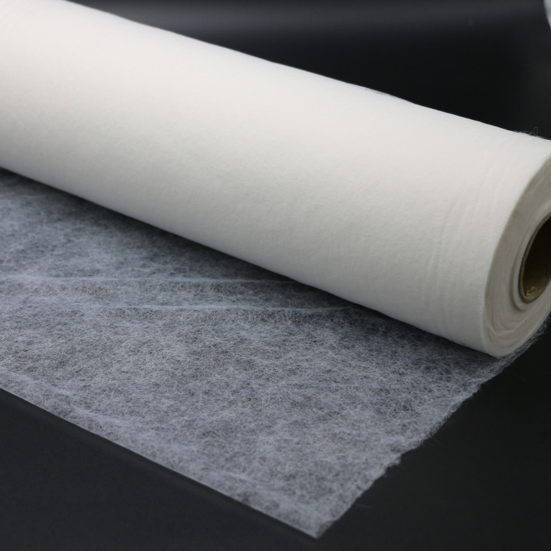
Why Is Fiber Orientation Important?
The importance of fiber orientation stems from the fundamental mechanics of composite materials. The fibers are the primary load-bearing constituent, providing strength and stiffness in their longitudinal direction. The matrix, while essential for transferring loads between fibers, protecting them, and providing environmental resistance, has significantly lower mechanical properties.
The Anisotropy Principle
In a unidirectional (UD) ply, the tensile strength and modulus in the fiber direction (longitudinal) can be orders of magnitude higher than in the perpendicular direction (transverse). This dramatic difference means that if a load is applied at an angle to the fibers, the laminate’s response is a complex combination of in-plane shear, transverse tension, and longitudinal tension.
As a result, an engineer cannot simply replace a metal component with a composite one without a thorough redesign. The design process must consider the direction of primary loads and define the fiber architecture accordingly. Improper orientation can lead to premature failure, with the laminate fracturing at loads far below its theoretical capability.
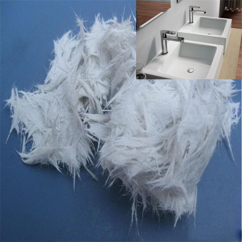
Basic Principles of Laminate Design
Ply Nomenclature and Orientation Angles
The orientation of a ply is defined by the angle between its primary fiber direction and a reference axis, typically the 0° axis. Angles are usually expressed in degrees, such as 0°, 90°, and ±45°. The standard notation for a laminate is a sequence of these angles, which defines the stacking order of plies from one surface to the other. For instance, a [0/45/-45/90]s laminate consists of four layers with a symmetric stack around its centerline.
Laminate Shorthand Notation
The layup can be represented using concise shorthand. The notation \([0/90]_{4S}\) or similar is frequently used to describe complex layups. Understanding this notation is essential for interpreting material specifications and design drawings. Common layups such as quasi-isotropic \([0/90/\pm45]_{s}\) are designed to provide balanced in-plane properties, mimicking an isotropic material at a macro level .
Symmetric vs. Asymmetric Laminates
– Symmetric Laminates: The stacking sequence is mirrored about the mid-plane. This is crucial to prevent warping or twisting of the laminate upon cooling from the curing process due to thermal expansion mismatches between plies.
– Asymmetric Laminates: The stacking sequence is not mirrored. While they can be useful for specific applications requiring tailored bending-twisting coupling, they are more prone to complex deformation and are less commonly used for primary structures.
Balanced Laminates
A laminate is considered balanced if for every +θ ply, there is an equivalent -θ ply somewhere in the sequence. This prevents extension-shear coupling, meaning that the laminate will not shear under a purely tensile load. A balanced layup is standard in many applications to ensure a predictable in-plane response.
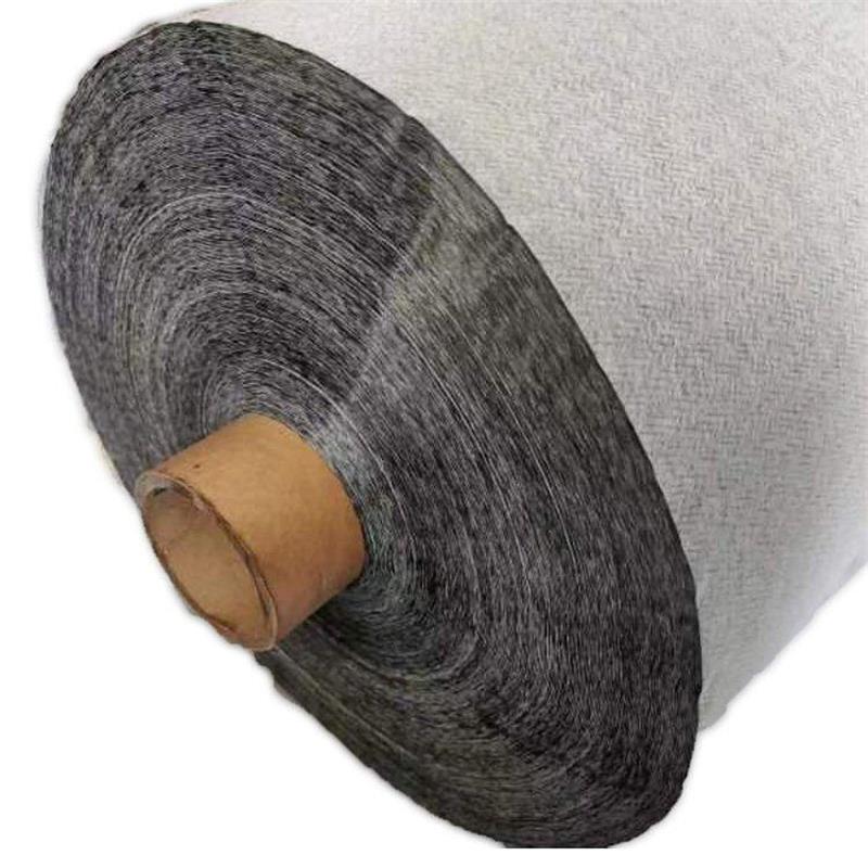
Manufacturing Processes and Their Influence
The manufacturing process significantly impacts the achievable fiber orientation and the overall quality of the laminate. While engineers can specify complex fiber angles, the manufacturing method must be capable of producing them reliably.
– Hand Lay-Up and Spray-Up: These are manual processes suitable for low-volume, large components. While relatively flexible, achieving consistent fiber orientation and high fiber volume fractions can be challenging. Orientation is primarily defined by the alignment of prepreg fabrics or fibers during placement.
– Automated Fiber Placement (AFP) and Automated Tape Laying (ATL): These computer-controlled processes offer high precision and repeatability. They are used for high-performance applications in aerospace, allowing for the “steering” of fibers along curved paths (fiber-steered design) to optimize performance for specific load paths .
– Pultrusion: A continuous manufacturing process where fibers are pulled through a resin bath and a heated die. This process inherently aligns all fibers along the product’s axis (0°), making it excellent for unidirectional profiles but less suitable for multi-directional laminates.
– Filament Winding: Used to produce hollow, axisymmetric parts like pipes and pressure vessels. Fibers are wound onto a mandrel at specific angles (e.g., helical, hoop) to withstand pressure loads effectively.
– Compression Molding: Often used with Sheet Molding Compound (SMC) or Bulk Molding Compound (BMC), where short fibers are randomly oriented. While random orientation provides isotropic properties in the plane, it sacrifices the specific strengths achievable with aligned continuous fibers.
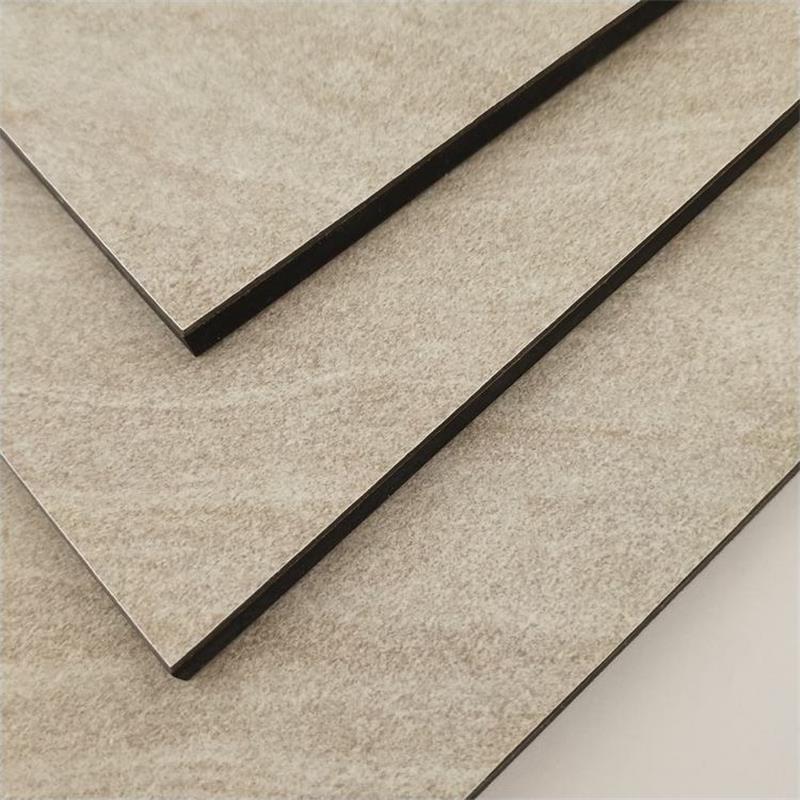
Effect of Fiber Orientation on Mechanical Properties
The influence of fiber orientation is a primary focus of composite research, as it dictates the laminate’s suitability for various engineering applications. A study on woven glass/polyester composites demonstrated the quantitative impact of orientation, finding that specimens with a 90° fiber orientation exhibited superior mechanical properties, including a maximum tensile load of 20 kN, compared to a 0° orientation which showed a significantly lower tensile load of 2.871 kN . This highlights the critical importance of matching fiber alignment to the primary stress direction.
Similarly, research on carbon fiber laminates with different stacking sequences found that unidirectional 0° laminates showed the highest tensile and flexural strengths, reaching up to 189.56 MPa and 275.93 MPa respectively, while a laminate with a 45° orientation exhibited the lowest tensile strength . These results underscore that aligning fibers with the load axis maximizes load transfer and material efficiency. The performance differential is so large that it underpins the primary economic justification for using composites: you only put strength where you need it.
Tensile Properties
When a laminate is subjected to a tensile load, the stiffness and strength are dominated by fibers oriented in the loading direction.
– Unidirectional (0°) Layup: Exhibits the highest tensile strength and modulus in the loading direction. The load is carried almost exclusively by the fibers .
– 90° Layup: The load is carried primarily by the matrix and the fiber-matrix interface, leading to significantly lower strength. This layup is typically avoided for primary structural loads.
– ±45° Layup: Provides good shear resistance but lower tensile strength compared to a 0° layup, as the fibers are not aligned with the load and experience a combination of tension and shear. The mechanical properties decline as the fiber orientation deviates from 0° .
Flexural Properties
Flexural strength (bending) is a combination of compressive and tensile stresses. The performance is highly dependent on the orientation of plies on the tensile and compressive faces.
– Unidirectional (0°) Layup: Shows the highest flexural strength, as the outer plies are aligned with the maximum tensile and compressive stresses. Simulations of 8-layer carbon fiber laminates confirmed the superior flexural strength of unidirectional configurations compared to those with angled plies .
– Hybrid Layups: Using a combination of 0° and 90° plies provides a balance of flexural strength and stiffness in multiple directions, albeit with some reduction in peak unidirectional performance. Research on GLARE laminates showed that a [0/45/0/45] layup provided the best impact resistance, demonstrating that flexural performance can be optimized for specific requirements through careful ply sequence selection .
Impact Properties
Impact resistance and toughness are critical for applications subject to dynamic loads.
– Orientation and Energy Absorption: Laminates with ±45° fibers are excellent at absorbing energy under impact, as the fibers can rotate and shear within the matrix, dissipating energy through delamination and matrix cracking. The [0/45/0/45] layup has been shown to achieve high impact resistance, often exceeding that of purely unidirectional laminates .
– Dynamic Mechanical Analysis (DMA): DMA studies on composites show that laminates with ±45° orientations dissipate significantly more energy during cyclic loading (higher loss modulus) compared to 0° or 90° orientations, as the off-axis fibers allow for greater internal friction .
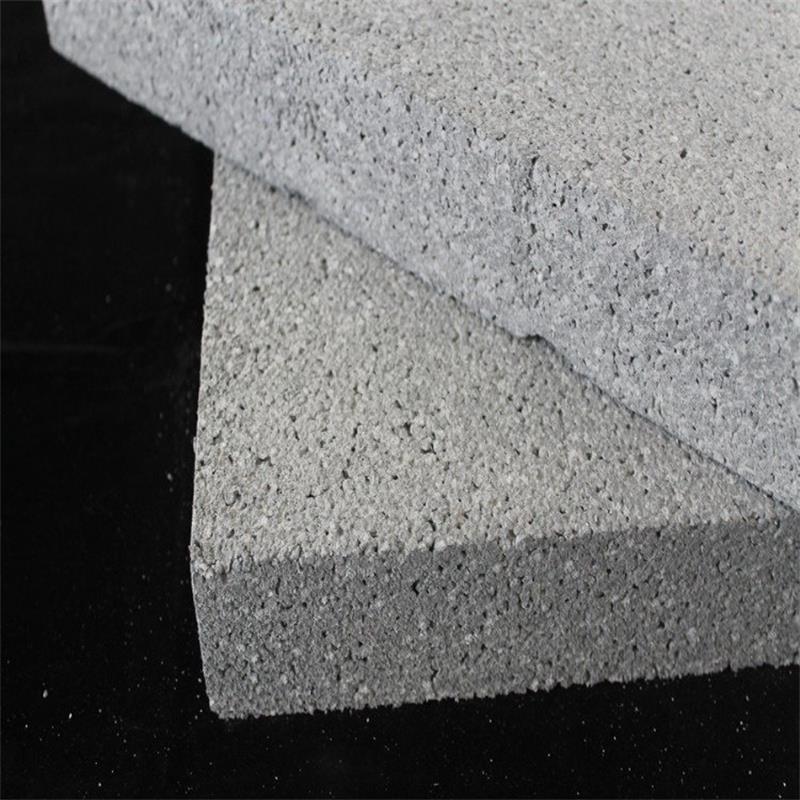
Summary of Mechanical Property Trends by Orientation
The following summarizes typical mechanical performance trends relative to fiber orientation:
Unidirectional (0°)
– Tensile Strength & Modulus: Very High
– Flexural Strength: High
– Impact Resistance: Low (brittle fracture)
– Shear Resistance: Low
Transverse (90°)
– Tensile Strength & Modulus: Very Low
– Flexural Strength: Very Low
– Impact Resistance: Low
– Shear Resistance: Low
Angle-Ply (±45°)
– Tensile Strength & Modulus: Moderate
– Flexural Strength: Moderate
– Impact Resistance: High (energy absorption)
– Shear Resistance: High
Quasi-Isotropic [0/90/±45]s
– Tensile Strength & Modulus: Balanced, Moderate
– Flexural Strength: Balanced, Moderate
– Impact Resistance: Good
– Shear Resistance: Good
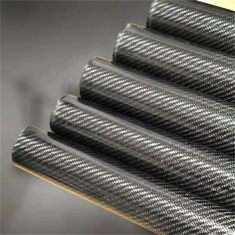
Key Advantages of Tailored Orientation
– Weight Reduction: By aligning fibers only in the directions of primary loading, material is used efficiently, resulting in structures that are significantly lighter than metal alternatives. Studies have demonstrated that optimizing fiber orientation and thickness can achieve weight reductions of over 5% compared to conventional designs without compromising strength .
– Design Flexibility: The ability to orient fibers in multiple directions allows the design of laminates with properties that are optimized for complex, multi-axial stress states. This is a significant advantage over isotropic materials.
– Cost-Effectiveness: While the material itself may be expensive, the efficiency in design reduces overall material usage and can lower operational costs (e.g., fuel consumption in aerospace and automotive applications).
Limitations and Design Considerations
– Manufacturing Constraints: Highly complex fiber orientations or those requiring tight radii may be difficult or costly to manufacture. For example, “fiber-steered” designs, while high-performing, require advanced AFP/ATL machinery .
– Design Complexity: Designing with anisotropic materials requires a deeper understanding of mechanics and failure theories (e.g., Tsai-Hill, Tsai-Wu) compared to designing with isotropic metals . The design matrix is a function of material properties, orientation, and stacking sequence.
– Failure Modes: Composites fail in complex ways. Delamination (separation of plies) and fiber-matrix debonding are common failure modes that can occur at stress levels well below the ultimate strength of the fibers, particularly under impact or compressive loads.
– Environmental Sensitivity: The properties of the laminate are also dependent on the matrix material, which can be susceptible to moisture and temperature variations.
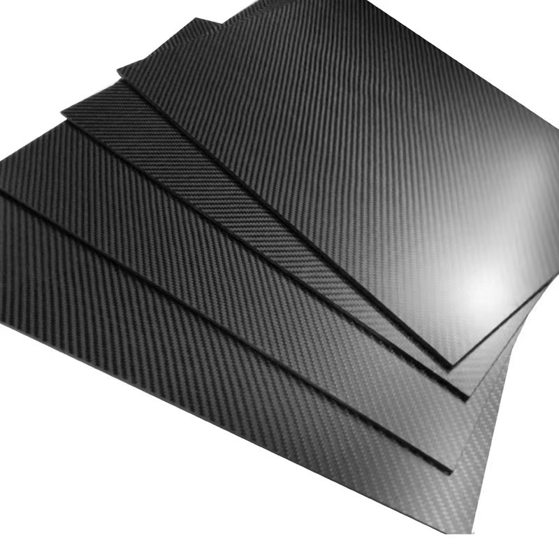
Industry Standards
Compliance with established industry standards is crucial for ensuring safety, reliability, and consistent quality in composite applications. These standards define testing methodologies, material specifications, and design requirements.
– ASTM Standards: The American Society for Testing and Materials (ASTM) provides numerous standards for composite testing. These include ASTM D3039 (tensile properties), ASTM D790 (flexural properties), and ASTM D7136 (drop-weight impact resistance).
– ISO Standards: The International Organization for Standardization (ISO) provides comparable standards, such as ISO 527-4 for tensile testing of polymer matrix composites and ISO 178 for flexural testing.
– Aerospace & Automotive Specifications: Industries like aerospace and automotive often have their own stringent testing protocols. For instance, aerospace composites are subject to rigorous qualification processes that involve testing thousands of coupons under various environmental conditions to certify a material system for use on commercial aircraft.
Design and Selection Guide
Step 1: Define Load Requirements
Accurately identify the magnitude, direction, and nature (static, cyclic, impact) of all primary loads that the component will experience during its service life. Finite Element Analysis (FEA) is a valuable tool in this stage.
Step 2: Select Laminate Architecture
Determine the orientation and stacking sequence of plies. Use established optimization methods, such as closed-form formulas based on Classical Lamination Theory, to determine the optimal angles for a given loading scenario .
– For uniaxial loads, consider a unidirectional (0°) layup.
– For bending, place 0° plies on the outer surfaces for maximum stiffness.
– For torsion or shear, incorporate ±45° plies.
– For multi-axial loads, use a quasi-isotropic stacking sequence.
Step 3: Choose Manufacturing Process
Select a manufacturing method that can accurately produce the specified architecture while meeting production volume and cost constraints. Consider the fiber steering capabilities and cost implications of the process .
Step 4: Optimize with Analysis
Use simulation tools (FEA) to verify the design’s performance. Employ optimization algorithms to fine-tune orientation angles and thickness distributions iteratively, often using a combination of finite element analysis and Taguchi methods or other statistical design-of-experiments .
Step 5: Test and Validate
Build prototypes and subject them to physical testing to validate the analytical predictions. Test results should be used to refine the design and ensure it meets all performance and safety requirements.
Common Problems and Misconceptions
– Misconception: Composites are just “stronger steel” . Composites are a design material, not a drop-in replacement. They are anisotropic, and as such, their design methodology is fundamentally different from that of isotropic metals.
– Misconception: All angle-ply laminates are the same. The performance difference between a [45/-45] layup and a [45/45] layup is substantial. A balanced layup (±θ) prevents unwanted extension-shear coupling, while an unbalanced layup may have significantly different properties .
– Problem: Inadequate Design for Compression. Composites are often strong in tension but can be weak in compression due to fiber micro-buckling. This must be accounted for.
– Problem: Environmental Degradation. Exposure to moisture and high temperature can degrade the matrix, reducing the load transfer capability of the interface. The composite’s performance in these conditions must be tested.
– Problem: Delamination. The interface between plies is a weak point in laminates. Impact damage or high out-of-plane stresses can cause delamination, which is often hidden from view and can significantly reduce the residual strength of the structure.
Frequently Asked Questions
What is the best fiber orientation for a composite to withstand tensile loads?
A unidirectional (0°) orientation, where all fibers are aligned with the direction of the tensile load, provides the highest tensile strength and modulus. This maximizes the load-bearing capacity of the reinforcement, as tests have shown that 0° laminates can exhibit very high maximum load values compared to off-axis orientations .
What is the “s” notation in a laminate layup sequence like [0/90/45/-45]s?
The “s” stands for “symmetric.” It indicates that the sequence of plies is mirrored about the central plane of the laminate. For example, [0/90]s means the layup is [0/90/90/0]. Symmetry is used to prevent warping or twisting when the laminate is subjected to temperature changes or curing stresses.
Why is a ±45° orientation used in many composite tubes and shafts?
A ±45° orientation provides high torsional (shear) stiffness and strength. It also offers good energy absorption characteristics. For this reason, it is often used in drive shafts, pressure vessels, and other structures where torsional loads are significant.
What does a quasi-isotropic layup mean, and why use it?
A quasi-isotropic layup, typically represented as [0/90/±45]s, has a balanced number of plies in the 0°, 90°, +45°, and -45° directions. This results in in-plane mechanical properties that are approximately equal in all directions (like a metal), making it a good starting point for parts that experience complex or unknown load directions.
How can the stacking sequence of plies influence impact resistance?
The stacking sequence dictates where the load is transferred between plies. A design like [0/45/0/45] can have better impact resistance, as the angled plies create more complex crack paths and allow for more energy absorption during an impact event compared to simply grouping all 0° plies together .
Can recycled carbon fibers be used in high-performance applications?
Yes, but their use presents challenges. Recycling processes shorten the fibers and randomize their orientation. However, researchers are developing technologies to reorient these fibers into highly aligned tapes that can achieve up to 88% of the mechanical properties of virgin carbon fiber composites .
What are Tsai-Hill and Tsai-Wu failure criteria?
These are mathematical criteria used to predict the failure of an anisotropic material under a multi-axial stress state. They are essential tools for composite design, helping engineers determine if a given laminate layup will survive its anticipated load conditions. They are often used in optimization algorithms to find the optimal fiber angle .
How does temperature affect the mechanical properties of a composite laminate?
Elevated temperatures can weaken the polymer matrix, reducing its ability to transfer stress between the fibers. This can lead to a reduction in overall strength, especially in compression and shear, as the matrix becomes softer. Conversely, extremely low temperatures can make the matrix more brittle.
What are the common failure modes for a composite laminate?
Common modes include fiber fracture, matrix cracking, delamination (separation between plies), and fiber-matrix debonding. Delamination is particularly critical as it can be difficult to detect visually and can propagate internally, significantly reducing the structural integrity of the part.
What is the role of the matrix material in determining laminate properties?
The matrix protects the fibers from environmental damage (e.g., moisture, chemicals), holds the fibers in their designated orientation, and transfers loads between broken fibers. While it contributes less to the in-plane stiffness and strength, its toughness and strength are critical for interlaminar shear and impact resistance. The dynamic mechanical properties of the composite, such as damping, are also significantly influenced by the matrix .
Is there a closed-form formula for optimizing fiber orientation?
Researchers have developed closed-form formulas, based on Classical Lamination Theory and failure criteria like Tsai-Wu, to provide an analytical solution for the optimum fiber orientation angle of symmetric laminates under in-plane loading. These formulas can serve as a rapid and effective starting point for design, applicable to glass/epoxy, carbon/epoxy, and aramid/epoxy composites .
What is “fiber-steered” design?
Fiber-steered design is an advanced approach where the fiber orientation is continuously varied across the component, rather than being constant within a ply. This is achieved through Automated Fiber Placement (AFP) and allows the material to be perfectly aligned with the local principal stresses, optimizing weight and structural performance .
The orientation of fibers in a composite laminate is the single most influential design parameter determining its mechanical performance. It defines the fundamental anisotropy that gives composites their unique engineering value. By understanding the relationships between ply angle, tensile strength, flexural behavior, impact resistance, and shear properties, engineers can unlock the full potential of these materials.
Effective design involves a systematic approach: defining the load environment, selecting an optimal stacking sequence using tools like Classical Lamination Theory and optimization algorithms, choosing a compatible manufacturing process, and finally, validating the design through rigorous testing against recognized standards like ASTM. Mastery of fiber orientation principles is the key to realizing the promise of lightweight, high-performance composite structures.
The future of composite design is moving toward more sophisticated optimization, with automated manufacturing enabling complex fiber paths that further enhance efficiency and performance. As the industry continues to evolve, the ability to understand and control fiber orientation will remain a cornerstone of engineering excellence in composite materials.
Carbon Fiber vs Glass Fiber Composites
The Multifunctionality of Polymer Composites
Thermoplastic vs. Thermoset Composites
 Carbon Fiber Composites: A Technical Analysis of Lightness, Strength, and Performance